I’m using an MCP3008 ADC and an MCP4131-103 (10k) digital potentiometer to try and create a sort of “adjustable voltage divider.”
For the project, the resistance I’m measuring will vary, and I hoped to use the MCP4131(http://www.kynix.com/Detail/61598/MCP4131-103E%2FMF.html) to adjust my reference resistor on the fly. Namely:
Vin
|
R1
|
|--Vout
R2
|
GND
I’m measuring and logging R1 (a material) over time, and it increases from maybe 500-20k Ohms over the duration of interest. If I use a fixed resistor for R2, I get poor resolution when the value is mismatched with the current value of R1. I hoped to have the digital pot adjust itself based on the running average so I also maintain my resolution.
I believe I have both the MCP3008 ADC and the MCP4131 working individually with my Raspberry Pi 3 using SPI, but they don’t seem to work like I expect in a voltage divider setup.
Wiring up the MCP3008 like this Adafruit guide, I used a voltage divider with a 10k resistor as R2 and the following formula to find R1:
v_out = adc * 3.3/1024
R1 = R2*(3.3 - v_out)/v_out

| resistor used |  calculated |
|---------------+-------------|
|          1000 |        1010 |
|          4700 |        4628 |
|         47000 |       46574 |
That confirmed that my ADC appears to be functioning well.
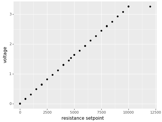
In addition, I cycled through settings for the MCP4131 and manually read the value between the high (3.3V) and wiper with an multimeter. In each case I’m sending a value of target resistance * 128/10000. I plotted the results and get:

That looked good enough for me to believe the pot is also connected and functioning correctly.
Now, when I try to setup a voltage divider like the above to test both the digital pot and the ADC together, I get wonky results. I’ve tried two configurations to troubleshoot, substituting the 4131 as either R1 or R2, with a fixed resistor as the other one used:
wiper pin of 4131 --|-- resistor -- GND
                    |
                    |
                   ADC

3.3V -- resistor --|-- wiper pin of 4131
                   |
                   |
                  ADC
Using a 10k resistor in the first configuration and setting the digital pot to 5k, I get a raw ADC reading of 403, or 1.3V. I’d have expected:
3.3V * (10000 / (10000+5000)) = 2.2V
This results in a calculation of:
10000*(3.3 - v_out)/v_out = 15384 # should be 5000
Swapping things around and using the second configuration, I get an ADC reading of 624 or 2.01V. I’d expect a value of:
3.3V * (5000 / (10000+5000)) = 1.1V
This results in a calculation of:
5000*(3.3 - v_out)/v_out = 3209 # should be 10000
I’m wondering if because the potentiometer is really a voltage divider in and of itself, it’s not behaving like I expect. Should I be, for example, changing my ADC Aref or GND to one of the R_a or R_b pins on the potentiometer? Or perhaps the error is in my code and I need to account for two voltage dividers in a row?
I haven’t found any examples of using a potentiometer as one of the resistors in a voltage divider. Unfortunately, a potentiometer is one, searching “using a potentiometer in a voltage divider” gets a ton of hits that simply explain what pots are.
Thanks for any guidance, and I’m happy to post whatever other information would be helpful.